
Finding the Signal in the Noise: Why Bandpass Filters are Essential for Wearables
Bandpass filters are essential for wearables because they isolate useful physiological signals such as heart rate and ECG from motion artefacts, baseline drift and electrical interference. This guide explains how high-pass and low-pass filtering work together, why filter design can affect signal timing and shape, and how firmware engineers implement digital filters to turn noisy sensor data into reliable health metrics.
Imagine you are standing in the middle of a screaming, sold-out stadium concert. The bass is vibrating your ribcage, tens of thousands of people are shouting, and somewhere in the middle of that deafening chaos, you are trying to listen to a friend whisper a secret from ten feet away.
That is exactly the environment your smart ring or medical wearable operates in every single second of the day.

When we look at the sleek glass of a modern wearable device, we are presented with a finished illusion. We see a clean, perfect heartbeat graph. We see beautifully formatted, stable numbers telling us our exact resting heart rate, blood oxygen level, or sleep stage. But as firmware engineers, people who spend their days writing the low-level code that actually pulls the raw electrical data out of these microscopic sensors, we know a secret: the raw data is an absolute mess.
The human body is loud. The electromagnetic environment around us is even louder. To find the delicate, rhythmic pulse of a human heart hidden inside a storm of electrical chaos requires one of the most fundamental and beautiful concepts in physics, electronics, and digital mathematics: The Bandpass Filter.
Whether you are a firmware developer dealing with I2C sensor registers, a software engineer building health apps, or just someone curious about how your Apple Watch actually works, this guide will explain the physics, the math, and the "why" behind signal filtering. We will go deep into the mechanics of how wearables actually process data, but no electrical engineering degree is required.
1. The Anatomy of a Signal: What Exactly Are We Looking For?
Before we can even begin to design a filter to remove the noise, we have to define what the "signal" actually is. What does a heartbeat look like to a computer?
In signal processing, we don't just look at how big a signal is (its amplitude or voltage); we care deeply about how fast it happens (its frequency). Frequency is measured in Hertz (Hz), which is simply a scientific way of saying "cycles per second."
Let’s look at a human resting heart rate. A normal heart beats somewhere between 60 and 180 beats per minute (BPM) depending on whether you are sleeping or sprinting.¹ If we divide that by 60 seconds, we get our physical frequency:
60 beats per minute = 1 beat per second (1Hz)
180 beats per minute = 3 beats per second (3Hz)
So, the fundamental rhythm, the biological drumbeat we are trying to hear, lives in a very narrow, slow-moving neighborhood: The 1Hz to 3Hz band.
However, a heartbeat is not just a smooth, rolling ocean wave. If you have ever looked at an ECG (Electrocardiogram) monitor in a hospital, you know that a heartbeat has a very specific shape. It starts with a small bump (the atria contracting), followed by a massive, sharp, jagged spike, and ends with a smooth recovery wave.
Medical professionals call that sharp spike the QRS Complex. It represents the massive electrical discharge that causes the main ventricles of your heart to pump blood throughout your body. Because that spike is so sharp and fast, it actually contains slightly higher frequencies, often up to 10Hz or 15Hz.²
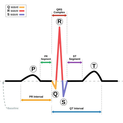
Therefore, our "golden signal" is not just a single number. It is a cluster of frequencies living mostly between 1Hz and roughly 15Hz. If we can isolate everything happening in this exact frequency band, we can reconstruct a perfect heartbeat. But as we are about to see, that is much easier said than done.
2. The Anatomy of Noise: The Stadium of Chaos
If the heart is whispering in that 1Hz to 15Hz zone, what is screaming over it? In the world of bio-signals, we have two massive enemies that sandwich our golden signal. We call them the "Floor" and the "Room."
Enemy #1: The Floor (Baseline Wander and Movement Artifacts)
Imagine trying to measure the height of a tiny toy boat on the ocean. If the ocean is perfectly flat, it is easy. But if the ocean has massive, 50-foot rolling swells, the toy boat is constantly floating up and down. The toy boat was the baseline, but it drifted because of the waves rolling effect.
This brings us to the physical reality of a wearable device. Every time you take a breath, your chest expands. Every time you swing your arm while walking, the wearable sensor shifts microscopically against your skin, changing the pressure and the optical reflection of the LEDs. Just like the shifting camera frame or the ocean swells, this physical movement creates massive, rolling electrical waves in the sensor data.
Because breathing and shifting are very slow, deliberate movements, they operate at extremely low frequencies, usually between 0.1Hz and 0.5Hz.³ In electronics, we call this slow drift "baseline wander." The baseline wander makes the entire heartbeat signal float up and down on a stormy mathematical ocean. If the signal is constantly drifting away from the center zero-line, it becomes mathematically impossible for a basic algorithm to accurately measure the height of the heartbeat peaks.

Enemy #2: The Room (50Hz/60Hz Mains Hum)
This is the invisible enemy, and it is absolutely everywhere. Everywhere you go, your bedroom, your office, a hospital ward, there are wires hidden in the walls carrying alternating current (AC) electricity to power your lights and outlets.
In most of the world (including India, the UK, and Europe), this power pulses at exactly 50Hz (or 60Hz in North America).⁴
Your body, being a giant bag of salt water, acts as a highly effective, fleshy antenna. It absorbs this 50Hz electromagnetic radiation from the power lines in your walls through a phenomenon called capacitive coupling.⁵ When a highly sensitive wearable sensor touches your skin, it picks up this massive 50Hz electrical hum along with your heartbeat.
Compared to your tiny biological pulse, the 50Hz wall power is deafening. It covers the entire signal in a thick layer of rapid, jagged, high-frequency electrical fuzz. If you look at raw sensor data on an oscilloscope, you often can't even see the heartbeat at all, it just looks like a thick, fuzzy caterpillar of electrical noise.

3. The Concept of Filtering: The Coffee Sieve Analogy
How do we separate the heartbeat from the slow 0.1Hz breathing and the fast 50Hz wall power? We have to filter it.
If you've ever made French press coffee or used a tea strainer, you already understand the physics of filtering. You have a mixture of liquid (the coffee you want) and solid grounds (the grit you don't want). You push a metal mesh screen through the mixture. The holes in the mesh are meticulously sized to be large enough to let water molecules pass through, but small enough to trap and block the larger coffee grounds.
In electronics and digital firmware, we do the exact same thing. But instead of filtering by physical size, we filter by frequency.
4. The Low-Pass Filter: Smoothing the Road
Imagine you are driving an off-road vehicle up a long, gentle hill on a road made of extremely rough, jagged cobblestones.
Your car is experiencing two types of physical movement simultaneously:
Low-Frequency Movement: The slow, gradual, multi-minute climb up the hill.
High-Frequency Movement: The rapid, violent, bone-rattling bump-bump-bump of the tires hitting the cobblestones every fraction of a second.
If you bolted the wheels directly to the metal chassis of the car with no suspension, your teeth would rattle out of your head. You would feel every single high-frequency bump transferred directly into your spine.
To fix this, automotive engineers invented the shock absorber. A shock absorber is quite literally a mechanical Low-Pass Filter.
A Low-Pass filter is designed to let slow (low-frequency) things pass through unaffected, while absorbing and destroying fast (high-frequency) things. The spring and piston of the shock absorber easily compress and expand to eat the fast cobblestone bumps. But it doesn't stop the car from slowly climbing the hill.

How this applies to a heartbeat: When a wearable sensor touches your skin, it picks up the slow heartbeat (the hill). But it also picks up the rapid 50Hz electrical hum from the power lines in your walls (the cobblestones).
In our firmware code, we apply a mathematical Low-Pass filter. We set what is called a "Cutoff Frequency." If we set our cutoff frequency to roughly 20Hz, we are telling the microcontroller: "Allow any data changing slower than 20 times a second to pass through, but aggressively average out and destroy anything changing faster than that."
The Result: The 50Hz electrical fuzz is crushed. The signal is now incredibly smooth.
The Problem: The Low-Pass filter didn't stop the slow, 0.1Hz baseline wander caused by your breathing. Our smooth signal is still drifting wildly up and down on the ocean wave.
5. The High-Pass Filter: Killing the Bass
To fix the slow drift, we need the exact opposite tool: a High-Pass Filter.
Think about the equalizer settings on your car stereo, television, or Spotify app. You usually have sliders for Bass and Treble.
Bass is a low-frequency sound. It is the slow, deep, omnidirectional rumble that vibrates your chest and the floorboards.
Treble is a high-frequency sound. It is the fast, sharp, directional ts-ts-ts of the cymbals and high-hats.
Imagine you are trying to listen to a bird chirping (a fast, high-frequency sound), but a massive diesel truck is idling right next to you (a slow, low-frequency rumble). The truck is so loud it is completely masking the bird.
If you turn down the "Bass" slider on your equalizer all the way to zero, you are applying a High-Pass Filter. You are telling the audio processor: "Only let the high, fast frequencies pass through, and heavily attenuate (block) the slow, deep ones." The deep rumble of the truck disappears, and the sharp chirp of the bird becomes crystal clear.

How this applies to a heartbeat: The slow drift caused by your breathing and body movement (0.1Hz - 0.5Hz) is the rumbling diesel truck.
In our firmware, we apply a mathematical High-Pass filter with a cutoff frequency of 0.5Hz. We tell the microcontroller: "Block any signal that takes longer than two seconds to complete a cycle." The algorithm acts like a mathematical anchor. It calculates that slow, rolling 0.2Hz baseline wander and dynamically subtracts it from the data array.
The Result: The "ocean" is flattened. The baseline wander is destroyed, forcing the signal to sit perfectly flat on the center zero-axis.
The Problem: A High-Pass filter alone would let all the rapid 50Hz electrical noise through!
6. The Hero: The Bandpass Filter (The Goldilocks Zone)
As we have seen, neither filter works perfectly on its own. The Low-Pass leaves the breathing drift. The High-Pass leaves the electrical fuzz.

The ultimate solution is to cascade them. When you run a signal through a High-Pass filter and then immediately run it through a Low-Pass filter, you create a Bandpass Filter.
A Bandpass filter creates a mathematical "window" or "band." It rejects everything that is too slow, rejects everything that is too fast, and only allows a specific, narrow band of frequencies to pass through untouched. This allowed region is called the Passband, while the blocked regions on either side are called the Stopbands.

By setting the lower edge of our Passband to 0.5Hz (using our High-Pass) and the upper edge to 20Hz (using our Low-Pass), we create a protective tunnel for the data.
The 0.1Hz breathing noise crashes into the left wall (the lower stopband) and is eliminated.
The 50Hz wall power crashes into the right wall (the upper stopband) and is eliminated.
The 1Hz to 15Hz heartbeat is in the "Goldilocks Zone." It slips straight through the window, clean, flat, and perfect, ready for a peak-detection algorithm to count the beats and calculate your BPM.
7. The Hidden Catch: Phase Shift and Distortion
Up until this point, filtering sounds like pure magic. Just apply the math, and the noise goes away, right?
Not quite. In the world of physics and signal processing, you never get something for nothing. When you apply a filter to a signal, you introduce a side effect called Phase Shift or Group Delay.
Filtering takes time. Even though a microcontroller runs at millions of cycles per second, the math itself relies on looking at past data to predict and smooth the current data.
Imagine you are trying to smooth out the stock market. To calculate a "7-day moving average," you literally have to wait 7 days to get your first data point. This means your smooth, filtered line is always lagging slightly behind the real, chaotic market.
Digital filters do the exact same thing. When the heartbeat passes through our Bandpass filter, the filter delays the signal in time. Worse, certain types of filters will delay different frequencies by different amounts of time! This is called non-linear phase distortion.⁶

If the sharp spike of the QRS complex is delayed by 10 milliseconds, but the slower recovery wave is delayed by 30 milliseconds, the physical shape of the heartbeat on the screen actually stretches and warps. For a fitness tracker counting basic BPM, a warped shape doesn't matter much as long as the spikes are countable. But for a medical-grade ECG trying to diagnose a heart attack (where the exact physical geometry of the wave is critical), phase distortion is a massive engineering problem.
8. How We Actually Build This in Firmware (The Deep Dive)
In the real world of embedded systems, how do we actually tell a tiny silicon chip to do this?
When we write baremetal C code for a wearable device, the sensor (like an IMU or an optical heart rate sensor) talks to the microcontroller over a communication bus like I2C or SPI. The sensor hands the microcontroller raw numbers at a specific "Sampling Rate." To capture a 15Hz heartbeat spike accurately, we must sample the sensor at least twice as fast (per the Nyquist-Shannon sampling theorem), but usually, we sample at 100Hz or 200Hz for high resolution.
This means we have an array of 200 raw integer numbers hitting the microcontroller every single second.
Historically, hardware engineers built physical filters using actual resistors, capacitors, and operational amplifiers soldered directly onto the printed circuit board (Analog Filters). But hardware is rigid. If you want to change the cutoff frequency from 20Hz to 15Hz, you have to throw away the circuit board and manufacture a new one. Plus, physical components take up critical space and cost money.
Today, we process the signals entirely in firmware using Digital Signal Processing (DSP). We take the incoming array of raw numbers, store them in a memory buffer, and run them through complex mathematical equations.
There are two primary types of digital filters we write in firmware: FIR (Finite Impulse Response) and IIR (Infinite Impulse Response).

The Math of an FIR Filter
An FIR filter is highly favored in medical devices because it does not cause the non-linear phase distortion we talked about earlier.⁷ It delays the entire signal uniformly, keeping the heartbeat's shape perfectly intact.
The core math behind an FIR filter is an operation called Convolution. Don't let the word intimidate you; it is just a process of multiplying and adding. The equation looks like this:
$$y[n] = \sum_{k=0}^{M-1} b_k \cdot x[n-k]$$
Here is the translation for normal humans:
$y[n]$ is the clean, filtered data point we want to output to the screen right now.
$x[n-k]$ represents the messy, raw sensor data we are currently receiving, as well as the history of the data we received a few milliseconds ago.
$b_k$ are the "coefficients." These are pre-calculated magic numbers that define the shape of our Bandpass window.
The sum (Sigma) symbol means we multiply the raw data by our magic coefficients, and add them all up.
Every single time a new sensor reading comes in, the microcontroller has to look at the last 50 or 100 readings, multiply each one by a specific coefficient, and add them all together to produce one single clean pixel.
Hardware Acceleration (CMSIS-DSP)
If you are doing this 200 times a second, and each time requires 100 multiplications and additions, a basic microcontroller will quickly max out its CPU, drain its tiny battery, and overheat.
This is where modern embedded engineering shines. If you are using a modern Real-Time Operating System (RTOS) like Zephyr on an ARM Cortex-M processor, you don't write that convolution math from scratch using simple C for loops.
Modern microcontrollers have dedicated hardware modules inside them called Floating Point Units (FPUs) and support SIMD (Single Instruction, Multiple Data) architecture. This allows the chip to perform a "MAC" operation (Multiply-Accumulate) in a single microscopic clock cycle.
As firmware engineers, we utilize optimized libraries like CMSIS-DSP (Cortex Microcontroller Software Interface Standard - Digital Signal Processing).⁸ Instead of writing the math, we call a highly optimized function provided by ARM. We hand the CMSIS-DSP library our raw data array and our magic coefficients, and the silicon hardware crunches the convolution math almost instantly, using a fraction of the battery power it would normally take.
The Takeaway
Building a wearable device is a constant battle against physics. The environment wants to bury the signal. The user's own body wants to distort it.\
The next time you look at the clean, pulsing heart icon on your smartwatch, take a moment to appreciate the invisible, microscopic war being fought inside the silicon. Millions of times a second, raw, chaotic data is being pulled from a sensor and run through heavy calculus equations. A mathematical window, a bandpass filter is standing guard, violently blocking out the electrical hum of the modern world and the physical chaos of your own body, all just to listen to the quiet, rhythmic whisper of your heart.
References:
professional, C. C. medical. (2026, June 5). What’s a normal heart rate? Cleveland Clinic. https://my.clevelandclinic.org/health/diagnostics/heart-rate
Technique-for-detection-of-QRS-complex-and-P-wave-from- ... (n.d.-j). https://www.ijert.org/research/technique-for-detection-of-qrs-complex-and-p-wave-from-ecg-signal-IJERTV2IS111162.pdf
Luo Y, Hargraves RH, Belle A, Bai O, Qi X, Ward KR, Pfaffenberger MP, Najarian K. A hierarchical method for removal of baseline drift from biomedical signals: application in ECG analysis. ScientificWorldJournal. 2013 May 20;2013:896056. doi: 10.1155/2013/896056. PMID: 23766720; PMCID: PMC3673325.
U.S.A. and Global AC Voltage & Frequency (hz) chart. New & Used Generators, Ends and Engines | Houston, TX | Worldwide Power Products. (2023, February 27). https://www.wpowerproducts.com/power-generation-resources/voltages-and-frequencies-by-country/
Eliminating power-line hum from ECG signals using time-series cyclic averaging and ADC clock locking | by Marco de Angeli | dec, 2025 | medium. (n.d.-c). https://medium.com/@marco_de_angeli/eliminating-power-line-hum-from-ecg-signals-using-time-series-cyclic-averaging-and-adc-clock-4f742d9cc378
Sarpal, Dr. S. (2024, December 5). Difference between IIR and fir filters: A practical design guide. ASN Home. https://www.advsolned.com/difference-between-iir-and-fir-filters-a-practical-design-guide/
Ieee. (n.d.). Finite Impulse Response Filter. IEEE Technology Navigator. https://technav.ieee.org/topic/finite-impulse-response-filter/
ARM-software. (n.d.). ARM-software/CMSIS-DSP: CMSIS-DSP embedded compute library for Cortex-M and cortex-a. GitHub. https://github.com/ARM-software/CMSIS-DSP


Comments